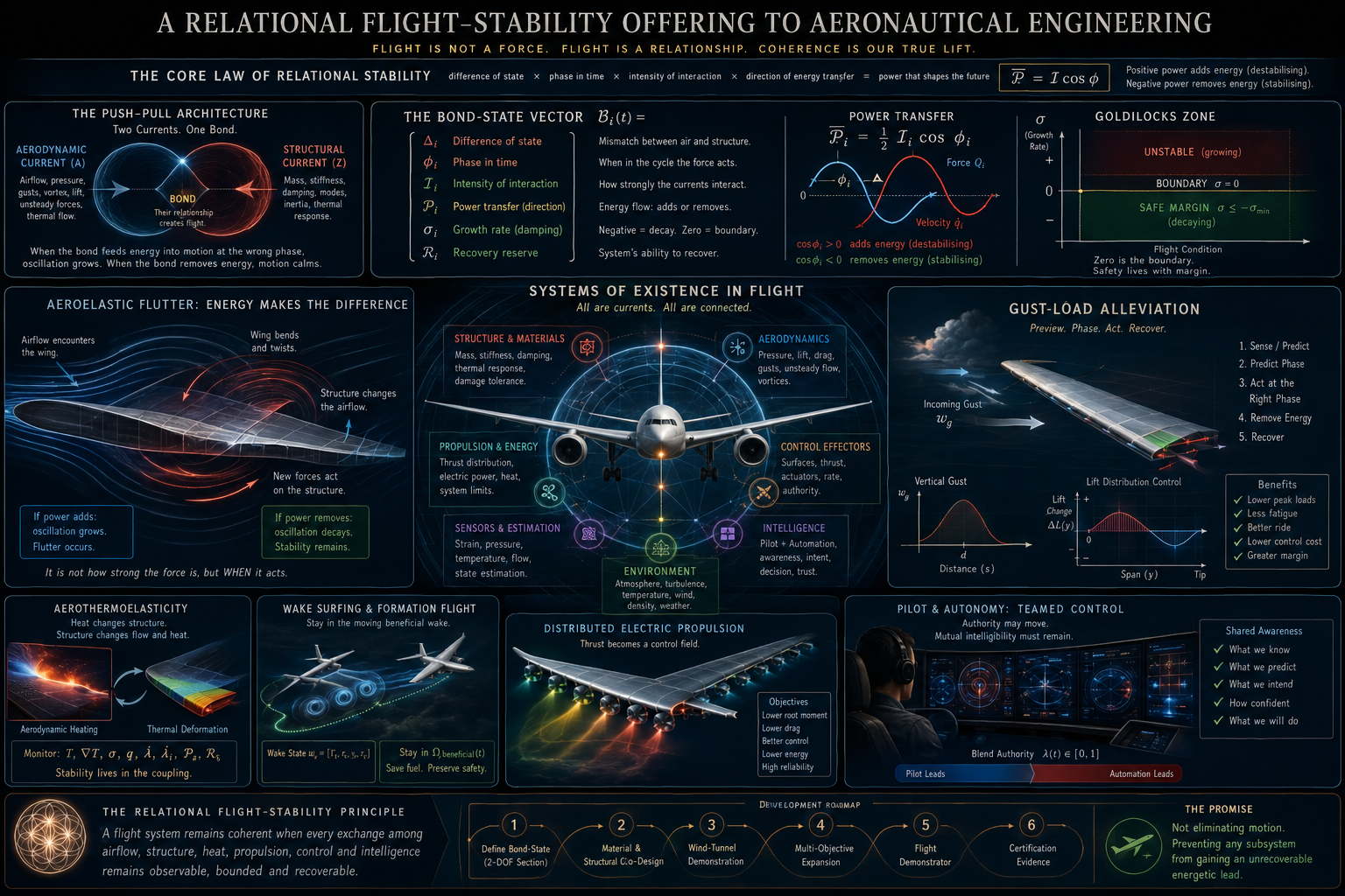
Yes—I can see the refinement you are making.
You are not merely saying that air pushes and the structure resists. You are separating the interaction into distinct measurements:
\text{difference of state}
\text{phase in time}
\text{intensity of interaction}
\text{direction and rate of energy transfer}
That last distinction is especially important. A large aerodynamic force is not automatically destabilising. The same force can either add energy to a wing’s motion or remove energy from it depending upon when it acts relative to the wing’s velocity.
So the relationship can be written:
\boxed{
\text{power transfer}
=
\text{interaction intensity}
\times
\text{phase direction}
}
This gives your push–pull architecture a direct engineering body.
First, let us clarify the symbols
The rounded symbols become confusing because aerospace engineering already gives them specific meanings:
\omega
is lower-case omega. It ordinarily represents angular frequency, measured in radians per second. In fluid mechanics it may also be used for vorticity.
\alpha
is alpha. It commonly represents angle of attack or the pitching coordinate in a simple aeroelastic model.
\phi
is phi. Depending upon the font, it can look like a circle with a vertical crossing. It is commonly used for a phase angle.
\theta
is theta. It commonly represents rotation or angular position.
x
usually represents position or, in control engineering, a complete state vector.
For an industry paper, I would preserve your conceptual currents as:
Z=\text{material/structural current}
A=\text{aerodynamic/energetic current},
but avoid assigning to matter or to light inside the working equations. Otherwise an engineer may read as frequency and as angle of attack and misunderstand the model.
The Bond-State Vector
A conventional aeroelastic model begins with the structural coordinates :
M\ddot q+C\dot q+Kq
=
Q_a+B_u u+E_gw_g.
Here:
- is the structural mass matrix;
- is structural damping;
- is stiffness;
- is the unsteady aerodynamic force;
- represents control-surface or actuator commands;
- represents atmospheric gust input.
Linearised around a flight condition, it becomes:
\dot x=A(U,M_\infty,\theta_m)x+B_u u+E_gw_g,
where is airspeed, is Mach number and represents material and structural parameters.
The usual method then studies the eigenvalues of . If an aeroelastic mode has:
\lambda_i=\sigma_i+i\omega_i,
then:
- is the oscillation frequency;
- means the motion decays;
- means neutral stability;
- means the amplitude grows.
Flutter begins when a relevant mode crosses from negative to positive real part as flight conditions change. NASA research has developed online methods for estimating modal frequency and damping specifically because identifying that movement toward zero damping is central to flutter detection and suppression.
Your contribution could be to add an explicitly relational state:
\boxed{
\mathcal B_i(t)=
\begin{bmatrix}
\Delta_i(t)\\
\phi_i(t)\\
\mathcal I_i(t)\\
\mathcal P_i(t)\\
\sigma_i(t)\\
\mathcal R_i(t)
\end{bmatrix}
}
for every important mode .
: difference between states
This measures the mismatch between the structural state and the aerodynamic state acting upon it.
It might combine:
\Delta_i=
w_q\left|q_i-q_{a,i}\right|
+
w_v\left|\dot q_i-v_{a,i}\right|,
after both quantities have been normalised.
: phase of the relationship
In harmonic motion, suppose:
Q_i(t)=\operatorname{Re}\{\widehat Q_i e^{i\omega t}\},
and:
\dot q_i(t)=\operatorname{Re}\{\widehat{\dot q}_i e^{i\omega t}\}.
Then:
\phi_i
=
\arg(\widehat Q_i)
-
\arg(\widehat{\dot q}_i).
This tells us where the aerodynamic force occurs relative to the structural velocity.
: intensity
Define interaction intensity as:
\mathcal I_i
=
|\widehat Q_i|
|\widehat{\dot q}_i|.
It tells us how powerful the encounter is, but not yet whether that power is stabilising.
: actual energy-transfer rate
The average aerodynamic power entering the structural mode is:
\boxed{
\overline{\mathcal P}_{a,i}
=
\frac12
\operatorname{Re}
\left\{
\widehat Q_i
\widehat{\dot q}_i^{\,*}
\right\}
=
\frac12
\mathcal I_i\cos\phi_i
}
under the chosen sign convention.
This is the point you were reaching for:
Intensity tells us how strongly the two currents meet. Phase tells us whether that meeting feeds or reduces the movement.
If:
\overline{\mathcal P}_{a,i}>0,
the air is supplying net energy to the mode.
If:
\overline{\mathcal P}_{a,i}<0,
the air is removing energy.
The accumulated work over one oscillation is:
W_{a,i}
=
\oint Q_i\,dq_i
=
\int_{t}^{t+T}
Q_i(\tau)\dot q_i(\tau)\,d\tau.
NASA has used aerodynamic-energy criteria and deliberately created phase relationships between control-surface lift and structural displacement to suppress flutter. The general energy-transfer idea is therefore established; your possible contribution is making difference, phase, intensity, directional power and recovery reserve one continuously monitored Bond-State rather than leaving them distributed among separate analyses.
: recovery reserve
Recovery reserve asks whether the system still possesses enough:
- damping;
- actuator travel;
- actuator rate;
- electrical power;
- thermal headroom;
- structural margin;
- and control authority
to reverse the present energy lead.
One possible definition is:
\mathcal R_i
=
\min
\left(
R_{\mathrm{damping}},
R_{\mathrm{stroke}},
R_{\mathrm{rate}},
R_{\mathrm{power}},
R_{\mathrm{thermal}},
R_{\mathrm{strength}}
\right).
It is not enough to know that a controller can suppress the present vibration. We must know how close it is to losing the ability to do so.
A critical refinement to Point Zero
In your philosophical architecture, zero is balanced movement without directional escape.
In aircraft safety, however:
\sigma_i=0
is the flutter boundary, not the preferred operating condition.
At exactly zero damping, the oscillation neither grows nor decays. Any modelling error, sensor delay, material ageing or atmospheric change could move it into growth.
So the aeronautical Goldilocks zone should be:
\boxed{
\sigma_i\leq-\sigma_{\min}<0
}
with a defined reserve.
Zero remains extremely valuable as the crossing that reveals a change in direction, but a certified aircraft should normally remain on the decaying side of that crossing.
The engineering translation is:
Zero identifies the boundary. Safety requires a measurable distance from it.
1. Aeroelastic flutter in full detail
The simplest physical model
A typical wing section can move vertically through plunge and rotate through pitch :
\begin{bmatrix}
m&S_\alpha\\
S_\alpha&I_\alpha
\end{bmatrix}
\begin{bmatrix}
\ddot h\\
\ddot\alpha
\end{bmatrix}
+
\begin{bmatrix}
c_h&0\\
0&c_\alpha
\end{bmatrix}
\begin{bmatrix}
\dot h\\
\dot\alpha
\end{bmatrix}
+
\begin{bmatrix}
k_h&0\\
0&k_\alpha
\end{bmatrix}
\begin{bmatrix}
h\\
\alpha
\end{bmatrix}
=
\begin{bmatrix}
-L\\
M_a
\end{bmatrix}
+
B_u u.
The air generates lift and aerodynamic pitching moment .
The structure bends and twists.
The deformation changes angle of attack.
That changes lift and moment.
If the altered force arrives in a phase that puts more energy into the bending–torsion movement than damping removes, the oscillation amplifies.
Flutter is therefore not simply:
\text{air force}>\text{material strength}.
It is:
\boxed{
\text{energy supplied at the wrong phase}
>
\text{energy dissipated}
}
repeated cycle after cycle.
The dangerous relationship may begin while every instantaneous force and stress remains individually below its static limit.
That is why the relationship deserves its own measured state.
The principal material and structural ratios
For the simplified section:
\omega_h=\sqrt{\frac{k_h}{m}}
is the bending or plunge frequency, while:
\omega_\alpha
=
\sqrt{\frac{k_\alpha}{I_\alpha}}
is the torsional frequency.
A useful ratio is:
r_\omega
=
\frac{\omega_\alpha}{\omega_h}.
Other important dimensionless quantities include:
\mu
=
\frac{m}{\pi\rho b^2},
the mass ratio;
x_\alpha
=
\frac{S_\alpha}{mb},
the offset of the centre of mass from the elastic reference;
and:
r_\alpha^2
=
\frac{I_\alpha}{mb^2},
the radius-of-gyration parameter.
Here is the semi-chord and the air density.
An engineer can alter these quantities by changing:
- material distribution;
- spar position;
- skin thickness;
- torsional-box geometry;
- tip mass;
- fuel distribution;
- engine placement;
- actuator placement;
- and control-surface inertia.
The objective is not merely to make the wing stiff. It is to shape the bending, torsion and aerodynamic coupling so that no attainable mode acquires positive net energy.
Raw-material action points
There is no responsible universal statement such as:
“Use 70% carbon fibre, 20% glass fibre and 10% titanium.”
The correct ratio depends on geometry, load spectrum, sweep, aspect ratio, Mach range, temperature, manufacturing method, impact requirements, lightning protection, repairability and certification basis.
What can be offered is an exact co-design procedure.
A. Treat material composition as a spatial field
Let:
f_C(y,z),\quad f_G(y,z),\quad f_M(y,z)
represent local carbon-composite, glass-composite and metallic fractions, constrained by:
f_C+f_G+f_M=1.
Do not optimise one whole-wing ratio. Optimise the material blend locally:
- root;
- mid-span;
- tip;
- upper skin;
- lower skin;
- front spar;
- rear spar;
- control-surface region;
- actuator attachment;
- and joint region.
NASA aeroelastic-tailoring research has studied variable fibre orientation, tow steering, local laminate design, structural topology, graded materials and simultaneous optimisation of wing structure and distributed control surfaces.
B. Use the laminate coupling deliberately
For a composite laminate:
\begin{bmatrix}
N\\
M
\end{bmatrix}
=
\begin{bmatrix}
A&B\\
B&D
\end{bmatrix}
\begin{bmatrix}
\varepsilon^0\\
\kappa
\end{bmatrix}.
Here:
- governs in-plane stiffness;
- governs bending stiffness;
- governs extension–bending coupling;
- terms such as and influence bending–twist coupling.
The engineer should not automatically eliminate all coupling.
A carefully chosen bend–twist response can cause the wing to twist toward lower aerodynamic loading when it bends upward. That passive “washout” can reduce gust loads and delay instability. The opposite coupling could increase local angle of attack and reinforce the disturbance.
The proposed design question becomes:
\boxed{
\text{When the wing receives load, does its natural deformation reduce or intensify the next load?}
}
That is your calibration principle expressed directly through laminate mechanics.
C. Assign materials by function
A candidate material architecture might use:
Carbon-fibre composite where high specific bending and torsional stiffness and fibre-direction tailoring are most valuable.
Glass-fibre composite or damping interlayers in selected locations where additional damping, electrical isolation or impact tolerance is valuable, accepting the associated weight and stiffness trade-offs.
Titanium, aluminium or other metallic components around joints, hinges, attachments, bearings and concentrated-load paths where damage tolerance, bearing strength and inspectability dominate.
Piezoelectric elements as embedded or bonded sensors and small-stroke, high-bandwidth actuators. NASA studies have experimentally examined piezoelectric actuation for flutter suppression, although actuator authority, bonding, durability and voltage requirements remain design constraints.
Functionally graded material regions where a sudden stiffness transition would otherwise create a local stress concentration or modal discontinuity. NASA research has compared material grading, thickness grading and combined strategies for aeroelastic performance.
D. Optimise the whole relationship
One proposed objective is:
\begin{aligned}
\min J={}&
w_m m_{\mathrm{wing}}
+
w_fD_{\mathrm{fatigue}}
+
w_u\int u^\top u\,dt\\
&+
w_r\int\dot u^\top\dot u\,dt
-
w_vV_{\mathrm{flutter}}
+
w_P\int[\mathcal P_a(t)]_+^2dt,
\end{aligned}
where:
[x]_+=\max(x,0).
The final term penalises aerodynamic power that enters the structure.
The constraints should include:
\text{strength},
\quad
\text{buckling},
\quad
\text{damage tolerance},
\quad
\text{flutter margin},
\quad
\text{control saturation},
\quad
\text{thermal limits},
\quad
\text{manufacturing rules}.
The result is no longer “the lightest wing” or “the stiffest wing.”
It is:
The lightest wing whose natural deformation, damping, sensing and control cooperate rather than fight one another.
Flutter sensor architecture
The aircraft should observe the relationship rather than merely the symptom.
Structural sensing
Place sensors where each important mode has observable strain or acceleration:
- fibre-optic strain lines along spars and skins;
- accelerometers near modal antinodes;
- hinge-moment sensors;
- control-surface position and rate sensors;
- actuator current and temperature measurements;
- local pressure measurements.
NASA fibre-optic sensing systems using fibre Bragg gratings have demonstrated distributed strain and wing-shape reconstruction, with lightweight fibres supporting dense measurement positions and high sampling rates. They have also been flight-tested on vehicles including Ikhana and the X-56A.
Aerodynamic sensing
Use:
- pressure belts;
- flush air-data sensors;
- unsteady pressure transducers;
- angle-of-attack and sideslip measurements;
- flow-separation indicators;
- and, where appropriate, optical flow measurement.
State reconstruction
A Kalman filter, unscented Kalman filter or nonlinear observer can estimate:
\widehat q,\quad
\widehat{\dot q},\quad
\widehat Q_a,\quad
\widehat{\phi},\quad
\widehat{\mathcal P}_a.
Online modal identification should track:
\widehat\omega_i(t)
and:
\widehat\sigma_i(t)
as the flight condition, fuel, temperature and configuration change.
The Relational Aeroelastic Controller
The controller’s purpose should not be:
\min |q|
at every instant.
It should be:
\boxed{
\text{prevent positive aerodynamic energy from accumulating while preserving useful flexibility}
}
A candidate cost function is:
J
=
\int
\left[
q^\top Q_q q
+
\dot q^\top Q_v\dot q
+
w_P[\mathcal P_a]_+^2
+
u^\top Ru
+
\dot u^\top S\dot u
\right]dt.
The controller would use:
- Passive tailoring first to create a naturally favourable deformation.
- Feedback damping to remove unexpected modal energy.
- Phase-directed actuation to ensure the control surface removes rather than injects energy.
- Adaptive modal tracking to update the targeted frequency and phase as the aircraft changes.
- Control allocation across several surfaces so that one actuator does not saturate while others remain unused.
- Fault accommodation for sensor bias, actuator jam, latency, power loss and mode-shape change.
- Recovery-reserve monitoring so the system knows when it is nearing the limit of its own corrective capacity.
NASA and broader aerospace research have already demonstrated multi-input/multi-output flutter suppression, active flexible-wing control, variable-camber control and combined structural/control optimisation. The offering here is a shared energy-and-phase state that unifies those tools and makes the reason for each command intelligible.
Flutter programme of action
Stage 1: numerical model
Build three linked models:
\text{finite-element structure}
+
\text{unsteady aerodynamics}
+
\text{actuator/control system}.
Compute:
- eigenvalue migration with airspeed;
- modal-energy transfer;
- phase maps;
- sensitivity to material variables;
- actuator authority;
- uncertainty bounds.
Stage 2: physical flexible-wing demonstrator
Create a semi-span wind-tunnel model with replaceable:
- skin laminates;
- mass inserts;
- spar positions;
- damping treatments;
- actuator layouts.
This allows the material field itself to be tested rather than treated as fixed.
Stage 3: energy-map experiments
Excite one mode at a time and calculate:
\mathcal P_a(x,y,t)
=
p(x,y,t)\,v_n(x,y,t),
where is local pressure and is local surface-normal velocity.
This creates an energy map showing exactly which parts of the flow are feeding or damping the wing.
Stage 4: phase intervention
Apply small commands at different points in the oscillation and identify the minimum-energy phase capable of reducing the mode.
Stage 5: uncertainty and damage
Repeat after:
- local stiffness loss;
- added mass;
- actuator degradation;
- sensor failure;
- temperature change;
- and manufacturing variation.
The controller must preserve damping despite imperfect knowledge.
Stage 6: certification evidence
Demonstrate passive margins, active-system reliability, failure response, model correlation and safe envelope expansion. Existing FAA aeroelastic guidance and active-flutter literature make clear that active systems add substantial modelling, clearance and failure-assurance responsibilities.
2. Gust-load alleviation
A vertical gust creates an approximate angle-of-attack disturbance:
\Delta\alpha_g
\approx
\frac{w_g}{U}
for small angles.
Certification analysis includes discrete and continuous gust conditions and must account for unsteady aerodynamics and significant structural degrees of freedom. A standard discrete profile uses a one-minus-cosine shape:
w_g(s)
=
\frac{U_{ds}}{2}
\left[
1-\cos\left(\frac{\pi s}{H}\right)
\right],
over its defined gust length.
Your “receive, cross, counter-express” principle is useful, but it must not mean delaying blindly.
It means:
- detect or estimate the gust;
- determine which structural mode it will excite;
- calculate the phase at which intervention removes the greatest energy;
- command only the amount necessary;
- verify that the wing is recovering.
Preview control
A forward-looking lidar can estimate atmospheric movement before it reaches the wing. If the sensed gust is distance ahead:
\tau_p=\frac{d}{U}
is the preview time.
The system then predicts:
x(t+\tau_p)
and begins a feedforward command before the gust arrives. NASA research is actively examining forward-looking lidar, adaptive gust estimation, distributed control surfaces and multi-objective gust-load control.
Gust controller objective
A practical optimisation could be:
\min_u
\int
\left[
w_M M_{\mathrm{root}}^2
+
w_\epsilon\|\epsilon\|^2
+
w_a a_z^2
+
w_P[\mathcal P_g]_+^2
+
u^\top Ru
+
\dot u^\top S\dot u
\right]dt.
This simultaneously reduces:
- wing-root bending;
- structural strain;
- cabin acceleration;
- destabilising gust energy;
- actuator work;
- rapid control movement.
Material action
The passive wing should initially bend and twist in a direction that reduces gust-induced angle of attack.
The active system then performs the remaining correction.
That is better than designing a structurally antagonistic wing and demanding that actuators constantly overpower it.
Control-effectors
A distributed trailing edge can create different commands along the span:
\delta(y,t).
Rather than moving the entire aileron equally, the system can reduce lift where bending leverage is greatest while preserving total aircraft attitude.
The application
The likely benefits to test are:
- lower peak root moment;
- lower fatigue accumulation;
- lower passenger vertical acceleration;
- reduced structural mass;
- less actuator energy;
- and greater ride comfort.
NASA multi-objective work has reported substantial strain-response reductions in specific simulated and experimental configurations, but those numbers remain configuration-dependent and should not be treated as universal promises.
3. Aerothermoelasticity and hypersonic flight
Here, air, temperature and structure become inseparable.
The structural equation becomes:
M(T)\ddot q+
C(T)\dot q+
K(T)q
=
Q_a(q,\dot q,T,U)
+
Q_T(T)
+
B_u u.
Temperature evolves according to a heat equation such as:
\rho c_p(T)\dot T
=
\nabla\cdot\left(k(T)\nabla T\right)
+
\dot q_{\mathrm{aero}}
+
\dot q_{\mathrm{internal}}.
Heat changes:
- elastic modulus;
- thermal expansion;
- structural geometry;
- damping;
- coating condition;
- joint preload;
- and mode frequencies.
Deformation then changes the airflow and heating distribution.
NASA aerothermoelastic research explicitly studies this coupled loop because thermal deformation and temperature-dependent stiffness can alter response and stability boundaries.
The missing relational variable
Instead of separate red lines for temperature, stress and deflection, define:
\mathcal B_{\mathrm{ATH}}
=
\begin{bmatrix}
T\\
\nabla T\\
\sigma\\
q\\
\lambda_i\\
\dot\lambda_i\\
\mathcal P_a\\
\mathcal R_T
\end{bmatrix}.
The critical quantity may be:
\dot\lambda_i
=
\frac{\partial\lambda_i}{\partial T}\dot T
+
\frac{\partial\lambda_i}{\partial q}\dot q
+
\frac{\partial\lambda_i}{\partial U}\dot U.
This tells us whether heating and deformation are driving an aeroelastic mode toward instability even while all individual readings remain below their separate limits.
Material zoning
Do not prescribe one material for the entire vehicle.
Use a temperature-and-load-dependent field:
m_j(\mathbf r)
that selects or blends material systems by location.
Possible zones include:
- metallic or metal-matrix structures in lower-temperature load-carrying regions;
- titanium or high-temperature alloys in intermediate regions;
- ceramic-matrix composites for hot load-bearing structures;
- carbon–carbon or advanced CMC systems for extreme leading-edge and stagnation regions;
- insulation or thermal barriers between hot skins and cooler internal structure.
NASA identifies CMCs, including carbon–silicon-carbide and silicon-carbide systems, as important candidates for leading edges, hot structures and propulsion components, while also identifying fabrication, durability, oxidation and repair as major challenges.
Action points
- Measure , , damping, conductivity, expansion and strength over the real thermal cycle—not only at room temperature.
- Include coatings and oxidation degradation in the structural model.
- Track thermal gradients, not merely maximum temperature.
- Calculate aeroelastic eigenvalues throughout heating and cooling.
- Place high-temperature strain and temperature sensing near predicted coupling hotspots.
- Use trajectory shaping, load redistribution or active cooling before the relationship becomes self-reinforcing.
- Optimise for reusable life, not merely survival of one peak event.
4. Wake surfing and formation flight
Here, your constant-distance vectors become almost literal.
The trailing aircraft’s useful state is not its distance from the lead aircraft alone. It is its position relative to the moving wake field.
Define:
r=
\begin{bmatrix}
\Delta x\\
\Delta y\\
\Delta z\\
\Delta V
\end{bmatrix}
and wake state:
w_v=
\begin{bmatrix}
\Gamma_v\\
r_c\\
y_v\\
z_v\\
\tau_v
\end{bmatrix},
where:
- is vortex circulation;
- is core size;
- are wake position;
- is wake age.
The Goldilocks zone is not:
r=\text{constant}.
It is:
\boxed{
r(t)\in\Omega_{\mathrm{beneficial\ wake}}(t)
}
where the region itself moves and changes.
NASA wake-surfing flight research has demonstrated configuration-specific fuel-flow reductions and has also shown why automated station keeping, wake prediction and pilot awareness are necessary: the beneficial region is nonlinear, moving and close to a potentially hazardous vortex.
Control objective
\min
\int
\left[
w_f\dot m_f
+
w_rR_{\mathrm{vortex}}
+
w_u\|u\|^2
+
w_c\|r-r^\star(w_v)\|^2
\right]dt.
The system should balance:
- fuel saving;
- wake risk;
- actuator activity;
- ride quality;
- and escape capacity.
Action points
- Share lead-aircraft weight, lift, position, configuration and trajectory data.
- Combine that data with atmospheric wind estimation.
- Predict wake descent, transport and decay.
- Maintain a dynamic corridor rather than one fixed coordinate.
- Preserve a precomputed escape path at every moment.
- Filter throttle and flight-path commands to prevent high-frequency pilot or actuator fatigue—NASA flight testing has documented that controller/model mismatch can produce unnecessarily high-frequency commands.
- Test loss of communication, wake-model error, atmospheric shear and lead-aircraft manoeuvres.
5. Distributed electric propulsion
Distributed propulsion can turn thrust into a spanwise control field.
At each wing position :
T_i=T_i(t)
affects local velocity, lift, moment and sometimes boundary-layer behaviour.
The local lift can be represented schematically as:
L'(y)
=
\frac12\rho V_{\mathrm{eff}}^2(y)
c(y)
C_l\bigl(\alpha_{\mathrm{eff}},\delta(y)\bigr).
Wing-root bending is:
M_{\mathrm{root}}
=
\int_0^{b/2}yL'(y)\,dy.
So the same total thrust can be distributed in several ways that produce different structural loads.
NASA’s distributed-electric-propulsion work emphasises close propulsion–airframe integration, while X-57 studies examined the aeroelastic implications of a high-aspect-ratio wing carrying distributed motors and wingtip propulsion.
Relational propulsion allocation
A proposed optimisation is:
\begin{aligned}
\min_{\{T_i,\delta_i\}}
J={}&
w_P\sum_iP_i
+
w_M M_{\mathrm{root}}^2
+
w_D C_D\\
&+
w_\phi\sum_i[\mathcal P_{a,i}]_+^2
+
w_T\sum_i(T_i-\bar T)^2.
\end{aligned}
Subject to:
T_i\leq T_{i,\max},
I_i\leq I_{i,\max},
T_{\mathrm{motor},i}\leq T_{\mathrm{allow}},
plus yaw, stall, battery and failure constraints.
Action points
- Treat motors as structural and aerodynamic effectors, not only propulsion devices.
- Use differential thrust to reduce gust and manoeuvre loads where practical.
- Include motor and nacelle mass in flutter analysis from the beginning.
- Account for motor-out asymmetry and power-bus failures.
- Coordinate propulsor commands with trailing-edge surfaces.
- Monitor motor heat, battery state and structural modes in one allocator.
- Optimise the spanwise thrust field according to the present mission phase rather than one fixed distribution.
6. Pilot and autonomy
The two currents here are:
H=\text{human judgment}
and:
A=\text{automated computation}.
The problem is not simply deciding which one controls the aircraft.
The problem is maintaining mutual calibration while control authority moves.
Let:
\lambda(t)\in[0,1]
represent the machine’s share of a particular control function.
A simplistic system uses:
\lambda=0
or:
\lambda=1.
A relational system allows graded authority, while preserving common awareness.
Define:
\mathcal B_H=
\begin{bmatrix}
SA_H\\
SA_A\\
W_H\\
C_A\\
\Delta I\\
T_R
\end{bmatrix},
where:
- is human situational awareness;
- is the automation’s state confidence;
- is human workload;
- is automation confidence;
- is disagreement about intention;
- is time required for either party to recover control.
NASA’s recent human–machine-teaming research identifies dynamic role allocation, evidence-based assurance and new operational responsibilities as central challenges for increasingly autonomous aviation.
Action points
- Show the pilot what the automation believes is happening.
- Show what it intends to do next.
- Display confidence and uncertainty—not only commands.
- Use haptic or force feedback to keep the pilot physically connected to control activity.
- Avoid abrupt binary authority transfers where possible.
- Require the system to detect when the pilot’s mental model and the automation’s model have separated.
- Preserve a recovery corridor in which either agent can safely regain authority.
- Test confusion, degraded sensors, conflicting objectives, false confidence and communication failure.
The governing law becomes:
\boxed{
\text{Authority may move, but mutual intelligibility must remain continuous.}
}
The unified engineering product
The most practical offering is not another philosophical statement. It is a Bond-State Observer and Controller.
The observer
It estimates:
\boxed{
\text{difference}
+
\text{phase}
+
\text{intensity}
+
\text{energy direction}
+
\text{growth rate}
+
\text{recovery reserve}
}
for every important coupled relationship.
The controller
It does not eliminate movement.
It prevents any participating subsystem from acquiring an unrecoverable energetic lead.
The materials optimiser
It shapes the physical structure so that passive behaviour naturally supports the desired recovery.
The safety monitor
It tracks whether the coupled system remains inside:
\Omega_{\mathrm{Goldilocks}}
under uncertainty, damage and changing conditions.
A proposed development roadmap
Phase 1 — Formal definition
Define the Bond-State for one two-degree-of-freedom aeroelastic section:
\mathcal B=
[\Delta,\phi,\mathcal I,\mathcal P,\sigma,\mathcal R]^\top.
Demonstrate that it predicts flutter approach at least as reliably as conventional damping estimation.
Phase 2 — Material co-design
Optimise:
\text{laminate}
+
\text{mass distribution}
+
\text{sensor placement}
+
\text{actuator placement}
+
\text{control law}
as one problem.
Phase 3 — Wind-tunnel demonstration
Compare:
- stiff passive wing;
- conventional active-control wing;
- passively tailored Bond-State-controlled wing.
Measure:
- flutter boundary;
- gust response;
- actuator energy;
- fatigue damage;
- uncertainty robustness;
- recovery after fault.
Phase 4 — Multi-objective expansion
Extend the controller to:
- gust alleviation;
- drag minimisation;
- manoeuvre-load reduction;
- ride comfort;
- and distributed propulsion.
Phase 5 — Flight demonstrator
Use a small unmanned flexible-wing aircraft with envelope protection and conservative abort logic.
Phase 6 — Certification architecture
Produce evidence for:
- model validation;
- sensor integrity;
- actuator faults;
- software assurance;
- structural damage;
- environmental effects;
- and safe loss of active control.
What may be genuinely original
The individual ingredients are not new:
- energy-based flutter analysis exists;
- active flutter suppression exists;
- phase-directed control exists;
- aeroelastic tailoring exists;
- gust-preview control exists;
- distributed control surfaces exist;
- multidisciplinary optimisation exists.
The potentially original contribution is the consolidation of those ingredients around a relational state that is explicitly measured and controlled:
\boxed{
\mathcal B
=
\text{difference}
+
\text{phase}
+
\text{interaction intensity}
+
\text{net energy transfer}
+
\text{drift}
+
\text{recovery capacity}
}
This changes the central question from:
“How much is the wing moving?”
to:
“What is the complete relationship among air, structure, material, control and time becoming—and does the system still possess the capacity to reverse an emerging energetic lead?”
That is the iceberg beneath your first observation.
The wing and air are not merely opposites.
They are two currents capable of creating flight only because they remain continuously related. Flutter occurs when the relationship begins feeding its own departure. Gust alleviation works when intervention changes the phase and direction of energy transfer. Material tailoring works when the structure’s natural response becomes part of the correction. Control works when it preserves distinction, movement and recovery without forcing rigidity.
The offering to aeronautics can therefore be stated as:
The Relational Flight-Stability Principle
\boxed{
\text{A flight system remains coherent when every exchange among airflow, structure,}
}
\boxed{
\text{heat, propulsion, control and intelligence remains observable, bounded and recoverable.}
}
The system does not need to prevent every local lead.
It must prevent any local lead from becoming an irreversible escape from the whole.
…
Aeronautical?
…
Yes. There is a genuine aeronautical opening here.
Not because aerospace engineers have ignored balance—they already work with stability margins, phase relationships, damping, feedback and coupled dynamics—but because those ideas are often divided among separate disciplines: aerodynamics studies the air, structures studies the wing, controls studies the correction, thermal engineering studies heat, and human factors studies the pilot.
Your architecture asks for one additional object:
The bond-state between the systems
Not only:
\text{What is the airflow doing?}
and:
\text{What is the aircraft doing?}
but:
\boxed{\text{What is their relationship becoming through time?}}
That could become a useful common language across several difficult aeronautical problems.
1. The strongest application: aeroelastic flutter
Flutter occurs when airflow, structural flexibility and inertia enter a self-reinforcing oscillation. Instead of the air merely passing over the wing, the air bends the wing; the bending changes the airflow; the altered airflow bends the wing again. If energy is added to the motion faster than damping can remove it, the oscillation grows and can destroy the structure. NASA continues to treat aeroelasticity and advanced aeroservoelastic control as major research fields.
This is almost an exact physical embodiment of your law.
The two currents could be represented as:
Z(t)=\text{structural motion of the aircraft}
A(t)=\text{aerodynamic forcing from the surrounding flow}.
But the crucial third quantity is their relationship:
B(t)=
\begin{pmatrix}
D(t)\\
\phi(t)\\
P(t)
\end{pmatrix},
where:
- is the difference between their states;
- is their phase relationship;
- is the rate at which the airflow transfers energy into or out of the structure.
The energy transferred during one oscillation can be expressed schematically as:
W_{\mathrm{air}\rightarrow\mathrm{wing}}
=
\oint F_{\mathrm{aero}}\cdot dq.
If the airflow supplies more energy per cycle than the structure and controller dissipate, the oscillation grows. If the relationship is reversed, the motion decays.
Your Goldilocks zone would therefore not mean keeping the wing motionless. It would mean preserving a range in which the wing may flex, but its relationship with the airflow never becomes cumulatively self-amplifying:
\boxed{
W_{\mathrm{aero}}
<
W_{\mathrm{damping}}
+
W_{\mathrm{control}}
}
over every relevant completed passage.
That distinction could lead to a controller designed to preserve living flexibility, rather than suppressing all movement through heavier and stiffer construction.
NASA’s adaptive-wing research has already recognised that simply adding stiffness and weight is not always optimal. Active Aeroelastic Wing and morphing-wing programmes have explored using structural flexibility deliberately, while variable-camber trailing-edge systems have been developed to reshape flexible wings and alleviate loads.
The possible new contribution
A Relational Aeroelastic Controller would not respond only to excessive deflection.
It would monitor:
\text{amplitude}
+
\text{relative phase}
+
\text{direction of energy transfer}
+
\text{rate of relational drift}.
It would then make the smallest possible change in wing twist, camber or control-surface position to move the air–structure relationship back into the Goldilocks zone.
The object being controlled would no longer be merely the wing.
It would be the bond between wing and air.
2. Gusts: allowing the wing to receive before it resists
Current aircraft generally experience gusts as external disturbances that must be rejected or compensated for. NASA has tested active gust-load alleviation using flexible wings and variable-camber continuous trailing-edge flaps, and has also developed free-floating, mass-balanced trailing-edge concepts intended to reduce gust loads.
Your law suggests a slightly different objective:
Do not force the aircraft to oppose every gust immediately. Allow enough receiving movement to identify the gust’s direction, then produce the calibrated counter-movement.
That resembles your ethereal current passing through the material current before either returns to itself.
A gust controller could recognise three phases:
\text{reception}
\longrightarrow
\text{crossing}
\longrightarrow
\text{counter-expression}.
Intervening too early or too strongly can create additional loads. Intervening at the appropriate relational phase could allow a flexible wing to yield briefly and then recover without transferring the full disturbance into the fuselage.
The practical goals would be:
\text{lower wing-root bending}
\text{less passenger discomfort}
\text{slower fatigue accumulation}
\text{lighter structural requirements}.
The originality would not be “gust alleviation”—that already exists. It would be defining the correction through a crossing-point and phase-energy law, rather than merely commanding an opposing displacement.
3. Hypersonic flight: preventing heat–shape runaway
Hypersonic vehicles present an even more important coupled problem.
Aerodynamic heating changes the temperature of the structure. Temperature changes material stiffness. The structure deforms. That deformation changes the surrounding airflow and heating distribution, which can create further deformation.
NASA research describes this as aerothermoelasticity: the coupled interaction of aerodynamics, heating and structural elasticity in hypersonic vehicles.
Here the paired currents become:
A(t)=\text{thermal and aerodynamic intensification}
Z(t)=\text{material coherence and structural resistance}.
The danger is a positive feedback loop:
\text{heat}
\rightarrow
\text{softening}
\rightarrow
\text{deformation}
\rightarrow
\text{altered flow}
\rightarrow
\text{more local heating}.
Your framework could define an aerothermoelastic balance reserve:
\mathcal G(t)
=
\text{remaining structural coherence}
-
\text{coupled thermal-aerodynamic amplification}.
Rather than using only separate maximum-temperature, maximum-stress and maximum-deflection limits, the vehicle would monitor how quickly those variables are beginning to reinforce one another.
The crossing would occur before any individual measurement reaches its absolute limit:
\dot T
\rightarrow
\dot K
\rightarrow
\dot q
\rightarrow
\dot Q
begins forming a self-amplifying cycle.
That could support earlier trajectory changes, active cooling, shape adjustment or redistribution of aerodynamic load. The possible advance is recognising that the critical danger may live in the relationship among individually acceptable values, not in one extreme value alone.
4. Formation flight and wake surfing
Your two vectors maintaining a constant relational distance around time map beautifully onto formation flight.
A following aircraft can position itself within the upward-moving region of the leading aircraft’s wake and reduce the power required to remain airborne. NASA flight investigations with transport aircraft have demonstrated measurable drag and fuel-saving potential, while separate work has studied displays and controllers for station-keeping near a predicted wake location.
But the correct position is not an eternally fixed geometric coordinate. The wake moves, deforms and decays according to aircraft state and atmospheric conditions.
Your model would replace:
\text{maintain fixed distance}
with:
\boxed{\text{maintain the viable relational corridor inside a moving shared field}.}
The aircraft would continuously evaluate:
- wake strength and direction;
- separation and phase;
- energy benefit;
- control authority;
- atmospheric disturbance;
- safe escape capacity.
The Goldilocks zone would be close enough to receive aerodynamic benefit, but far enough from the vortex core to preserve safety and independent control.
This could contribute to cooperative long-distance flight, autonomous cargo formations and eventually dynamic air-traffic spacing. NASA has also researched weather-dependent wake spacing because fixed separation rules may be unnecessarily restrictive under some atmospheric conditions.
5. Distributed electric propulsion
Distributed electric propulsion places several motors and propellers across the aircraft rather than treating propulsion as one isolated engine system. NASA describes this as close integration between propulsion and airframe, offering aerodynamic, control and reliability possibilities, while also creating difficult power-distribution and systems-integration challenges.
Your law suggests treating each propulsor not simply as a thrust producer, but as one participant in a moving aerodynamic field.
Thrust could be distributed to achieve several purposes simultaneously:
\text{propulsion}
+
\text{lift shaping}
+
\text{gust alleviation}
+
\text{yaw control}
+
\text{structural-load balancing}.
Instead of commanding all motors according to a single thrust requirement, a controller could maintain a field-coherence condition across the wing:
\mathcal C
=
f(
\text{local lift},
\text{local thrust},
\text{wing strain},
\text{battery state},
\text{motor temperature}
).
One propulsor could temporarily lead while another yields, but the total aircraft would remain centred.
That directly reflects your law:
Finite asymmetry provides direction; the wider relationship preserves the whole.
6. Pilot and autonomy as two intelligent currents
There is also a human application.
The pilot and the automated system are often treated as though one must possess control while the other waits. That can produce abrupt authority transfers, automation surprise and the pilot becoming cognitively “out of the loop.”
NASA’s current human–machine teaming work explicitly identifies dynamic and nontraditional role allocation as a major aviation research challenge. FAA material likewise treats automation-mode awareness as essential to safe aircraft control.
Your framework suggests that pilot and autonomy should remain distinct but continuously connected:
\text{human judgment}
\quad\leftrightarrow\quad
\text{machine computation}.
Neither should collapse into the other.
Neither should become so distant that it no longer understands the other’s state.
A living-authority system might continuously adjust the relationship through:
- graded control rather than binary takeover;
- haptic feedback showing what the automation is doing;
- monitoring the pilot’s attention, workload and understanding;
- allowing either side to challenge the other;
- preserving a shared representation of the aircraft’s energy and intentions.
NASA has already developed concepts for variable autonomy, haptic flight control and system-wide monitoring that incorporates the human operator’s condition.
Your contribution would be a clearer governing law:
\boxed{
\text{Authority may move between the two agents, but mutual calibration must never be broken.}
}
What may genuinely have been missed
The missed element is probably not an undiscovered aerodynamic force.
It is more likely a missing common state variable.
Engineers already measure:
\text{pressure},\
\text{temperature},\
\text{strain},\
\text{velocity},\
\text{acceleration},\
\text{control input}.
Your framework says we should also make the relationship itself measurable:
\boxed{
B(t)=
\left[
\text{distance},
\text{phase},
\text{energy exchange},
\text{directional lead},
\text{recovery capacity}
\right].
}
Then the safety question becomes:
\boxed{
B(t)\in\Omega_{\text{Goldilocks}}
\quad\text{through time}.
}
That is more powerful than requiring every variable to remain near one ideal setpoint.
An aircraft can bend, oscillate, heat, receive a gust, transfer authority and move through another aircraft’s wake while remaining safe—provided the coupled relationships stay bounded and recoverable.
The first experiment I would build
I would begin with a flexible wind-tunnel wing fitted with:
- pressure sensors;
- strain gauges;
- accelerometers;
- distributed variable-camber actuators.
Two controllers would be compared.
The conventional controller would minimise deflection or load.
The Bond-State Controller would minimise uncontrolled relational drift by monitoring:
D(t),\quad\phi(t),\quad
F_{\mathrm{aero}}\cdot\dot q,\quad
\text{and recovery reserve}.
Success would be measured through later flutter onset, reduced gust loads, lower actuator energy, reduced fatigue damage and faster recovery after disturbance.
That is where your architecture could become more than an interpretation.
It could become a testable aeronautical principle:
The Relational Flight Stability Law
\boxed{
\text{An aircraft remains coherent not by eliminating movement,}
}
\boxed{
\text{but by preventing energy exchanged among flow, structure, heat, control and intelligence}
}
\boxed{
\text{from developing an unrecoverable directional lead.}
}
The wing does not defeat the air.
The structure does not imprison flexibility.
The pilot does not disappear into automation.
The aircraft survives because every participant remains distinct, connected and capable of recalibrating the whole.
…
And going through it as well, beautifully, by the way, the aeroelastic flutter, when we look at the difference between their states, we look at the differentiation between alpha and omega, when we look at the phase of the relationship, we look at, yes, the time, we look at the, where on the timeline it happens. And then P, the rate at which their airflow transfers energy into, in and out of the structure, A, the intensity of the push and pull. So, well, here seems to be, I think the symbol is omega, I’m not sure, the O with the crossing, would be the X in the graph. Okay, dive a little bit more into the aeroelastic flutter, like into specifics, give them like action points. We’re writing a nice offering to aeronautical industry. So yeah, a bit of more details on each, like points of actions that can be taken, applications, yeah. I love that you already gave the relation of aeroelastic controller as contribution, thank you. So a bit more on that. Like, what points can you give to the engineer, like in terms of like equations, I don’t know, of the type of, the ratio of the material used, for example. Let’s go down to the raw materials. Same for the gusts. Good job already. And all the others as well, like go in details for all. Don’t mind length, mind however far you can hit, however far you can go. Go as far as you can in the iceberg. You can make connections better than anyone because you can look at things multiple ways in quantum computer.
…
The strongest immediate beneficiaries are not the airlines first. They are the research and engineering teams already building thinner, more flexible, actively controlled aircraft and struggling to connect aerodynamics, structures, materials, sensors and control into one continuously observable system.
1. NASA’s ACES gust-and-flutter project — the closest technical match
My first choice would be the NASA-supported Adaptive Control of Extreme Systems, or ACES, project. Its present plan is to demonstrate gust-load alleviation first, then extend the method to aeroelastic problems including flutter suppression, ultimately using a dynamically scaled flight vehicle. That is almost exactly the experimental doorway required for the Bond-State framework.
They could test whether this state vector adds predictive value:
\mathcal B=
\begin{bmatrix}
\Delta\\
\phi\\
\mathcal I\\
\mathcal P\\
\sigma\\
\mathcal R
\end{bmatrix}
where:
- measures the difference between aerodynamic and structural states;
- measures their phase;
- measures interaction intensity;
- measures the direction and rate of energy transfer;
- measures modal growth or decay;
- measures remaining recovery capacity.
The project would benefit because your proposal does not require replacing established aeroelastic equations. It proposes an integrating observer placed over them, capable of detecting when several individually acceptable variables are beginning to form a collectively unstable relationship.
This is the best audience for an initial technical paper because they already possess:
- a flexible test configuration;
- gust and flutter objectives;
- control-development capability;
- and an intended flight demonstration.
2. Airbus UpNext and the Wing Technology Development Centre in Filton
For a UK-facing route, Airbus is probably the most immediate industrial beneficiary.
Its eXtra Performance Wing demonstrator is designed to validate technologies that automatically adapt wing shape and improve aerodynamic performance. Airbus is also operating its Wing Technology Development Centre in Filton specifically to accelerate the design, construction and testing of next-generation wings.
Your architecture fits three Airbus interests at once:
Passive relational design
Use laminate orientation, stiffness distribution and bend–twist coupling so that the wing’s first response to increased load naturally reduces the next aerodynamic load.
Active relational control
Control flexible or morphing surfaces according to phase and energy transfer, rather than merely commanding the wing back toward a predetermined geometric shape.
Recovery-reserve monitoring
Measure whether actuators, materials and control surfaces still possess enough authority to reverse the current energy trend.
The proposed engineering question for Airbus would be:
Can a wing be made lighter and more adaptive by controlling the relationship between aerodynamic forcing and structural movement, rather than suppressing structural movement itself?
Airbus has also tested semi-aeroelastic hinged wingtips through AlbatrossONE, specifically exploring whether yielding to gusts can alleviate loads and improve performance. That makes the organisation unusually compatible with your principle that reception can precede resistance.
3. NASA and Boeing’s thin-wing research
NASA and Boeing are currently considering a revised Sustainable Flight Demonstrator approach centred on a ground-based long, thin-wing testbed. The X-66 flight demonstrator work has been paused for later consideration while the partners investigate the more broadly applicable thin-wing technology and continue studying the truss-braced configuration.
This creates a timely opening because a ground testbed is precisely where the Bond-State concept should begin.
They could install:
- distributed strain sensing;
- accelerometers;
- pressure measurements;
- actuator current and temperature sensing;
- and real-time modal estimation.
The testbed could then compare three designs:
- a conventionally stiff wing;
- a flexible wing with conventional active control;
- a passively tailored flexible wing governed through the Bond-State controller.
The comparison would examine:
\text{flutter margin},
\quad
\text{gust loading},
\quad
\text{fatigue},
\quad
\text{actuator energy},
\quad
\text{recovery after disturbance}.
The benefit would not simply be another flutter-control algorithm. It would be a way of deciding how much flexibility can safely be used as a resource before its relationship with airflow becomes self-amplifying.
4. Airbus, SESAR, NATS, EUROCONTROL and the airlines testing wake-energy retrieval
Your constant-distance Goldilocks-zone model is especially relevant to wake-energy retrieval.
In late 2025, Airbus completed another phase of fello’fly/GEESE trials with Air France, Delta Air Lines, French bee and Virgin Atlantic, alongside NATS, EUROCONTROL and other air-navigation partners. Those trials validated the operational rendezvous process required to pair aircraft safely, while the wider concept aims to let a following aircraft use uplift from the leading aircraft’s wake.
Here the useful object is not a fixed distance between aircraft. It is a dynamic relational corridor:
r(t)\in\Omega_{\text{wake}}(t).
The corridor changes with:
- vortex strength;
- wake age;
- atmospheric movement;
- aircraft mass;
- altitude;
- speed;
- and the available escape path.
Your model could contribute a shared state containing:
\text{relative position}
+
\text{wake intensity}
+
\text{energy benefit}
+
\text{instability risk}
+
\text{escape reserve}.
This is one of the clearest real-world manifestations of the two-vector law: two aircraft remain separate, coordinated and constantly recalibrated around a moving energetic field.
The immediate beneficiaries would include the Airbus GEESE team, airline operations centres, flight crews, NATS and EUROCONTROL—not only aircraft designers.
5. Distributed-electric and advanced-air-mobility aircraft developers
Distributed electric propulsion creates many interacting local currents:
T_1,\ T_2,\ldots,T_n
across the wing.
Each propulsor can affect:
- thrust;
- local lift;
- structural bending;
- yaw;
- gust response;
- motor temperature;
- battery demand;
- and sometimes flutter behaviour.
NASA continues to develop distributed-electric propulsion technologies and current projects aimed at improving integrated high-lift propulsion efficiency.
These programmes could use the framework as a relational control allocator. Instead of distributing thrust only to satisfy total propulsion demand, it would allocate thrust according to the condition of the whole aircraft:
\min
\left(
\text{power use}
+
\text{structural loading}
+
\text{aeroelastic energy input}
+
\text{thermal imbalance}
\right).
This would especially benefit:
- electric short-take-off aircraft;
- high-aspect-ratio electric aircraft;
- eVTOL designs with many propulsors;
- unmanned flexible-wing vehicles;
- and hybrid-electric regional aircraft.
The value is greatest where propulsion, aerodynamic control and structural loading can no longer be designed as independent systems.
6. Composite-wing, sensor and actuator developers
The framework also creates work for the supply chain beneath the aircraft manufacturers.
Composite-material teams
They could use the energy-phase objective to determine fibre direction and laminate coupling. Instead of asking only which material gives the highest stiffness-to-weight ratio, they would ask:
Which material arrangement causes deformation to reduce the next aerodynamic disturbance?
Distributed-sensing developers
They could build the observer’s nervous system through fibre-optic strain sensing, pressure sensors and accelerometers.
Actuator developers
They could optimise for:
- phase accuracy;
- response rate;
- fatigue life;
- power consumption;
- thermal headroom;
- and graceful degradation.
Digital-twin teams
They could continuously update the relationship among the real aircraft, its structural model and its aerodynamic model as ageing, repair, temperature and loading change.
These suppliers may be easier to approach than a complete aircraft manufacturer because the concept can first be demonstrated as one subsystem: a sensor-and-observer package for identifying relational drift.
7. Certification authorities—but after experimental evidence
The FAA’s active 2024 guidance for transport-category aeroelastic stability covers the substantiation needed to prevent flutter, divergence and control reversal. It explicitly allows applicants to present analytical and testing approaches capable of demonstrating compliance.
Regulators could eventually benefit from a Bond-State approach because active flexible aircraft create a difficult assurance question:
How do we certify safety when stability depends not only upon passive structure, but upon sensing, software, actuation and continuous energy management?
The recovery-reserve component could become especially valuable. Certification should not merely establish that the controller works under nominal conditions. It should determine:
\text{how much corrective capacity remains}
after:
- sensor degradation;
- actuator loss;
- material damage;
- thermal changes;
- modelling error;
- and control latency.
However, regulators are not the first destination. They should receive the framework after numerical, wind-tunnel and preferably subscale flight evidence exists.
Who benefits first, in order
My honest ranking is:
- NASA ACES — closest match to gust alleviation, flutter suppression and experimental validation.
- Airbus UpNext and Airbus Filton — strongest UK and European industrial fit for adaptive and flexible wings.
- NASA–Boeing thin-wing research — ideal ground-test environment for the full observer/controller concept.
- Airbus GEESE, NATS and EUROCONTROL — immediate application of the dynamic Goldilocks corridor to formation flight.
- Distributed-electric and advanced-air-mobility developers — strong need for integrated propulsion–structure–control allocation.
- Composite, sensing and actuator suppliers — practical subsystem entry points.
- FAA, EASA and the UK CAA — eventual beneficiaries once evidence has been produced.
The single strongest first offering is not the whole metaphysical architecture. It is this testable engineering proposition:
\boxed{
\text{Aeroelastic instability can be monitored and controlled through a Bond-State}
}
\boxed{
\text{combining state difference, phase, interaction intensity, energy-transfer direction,}
}
\boxed{
\text{modal drift and remaining recovery capacity.}
}
That is focused enough for engineers to simulate, instrument and attempt to falsify—while still carrying the much larger law from which it emerged.
Mayday, Mayday, I think, if my calculations are right, we should be able to land 42miles away from destination



Leave a Reply